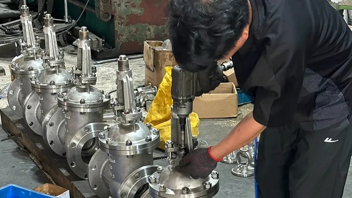
Every pressure system has a limit beyond which equipment can fail. Control systems and operators keep pressure within that limit during normal running, but they cannot cover every upset: a blocked outlet, a control valve failing shut, external fire or thermal expansion of trapped liquid. The safety relief valve is the mechanical device that deals with those events without needing power or a signal.
This article explains the terminology, the operating principle, the main designs and the points buyers and engineers should check when specifying one.
Safety valve, relief valve and safety relief valve
The terms are used loosely, but they have distinct meanings in the relief valve standards. A safety valve opens fully and rapidly, often called pop action, and is normally used on gas and steam. A relief valve opens in proportion to the overpressure, which suits liquids. A safety relief valve is designed to work in either role, depending on the application. Many specifications use the broader term pressure relief valve (PRV) to cover all of them.
The distinction matters when you specify one. A valve with pop action on liquid service may chatter, and a proportional valve on steam may not release enough flow quickly. State the fluid and phase clearly.
How a spring-loaded valve works
In the most common design, a spring pushes a disc onto a nozzle. The spring is compressed to a set load. Under normal conditions, system pressure acting on the disc produces a force below the spring load, so the valve stays closed. When pressure reaches the set pressure, the force overcomes the spring and the disc lifts.
On gas and steam, a small increase in pressure is enough to produce a rapid lift because the escaping fluid acts on an enlarged area, such as a huddling chamber or disc holder. This gives the snap action associated with safety valves. The valve discharges until pressure falls to the reseating pressure, which is slightly below the set pressure. The difference between set and reseating pressure is the blowdown.
Key terms
| Term | Meaning |
|---|---|
| Set pressure | Pressure at which the valve begins to open under service conditions |
| MAWP | Maximum allowable working pressure of the protected equipment |
| Overpressure / accumulation | Pressure increase above set or MAWP allowed while the valve discharges |
| Blowdown | Difference between set pressure and reseating pressure |
| Back pressure | Pressure at the valve outlet, from the discharge system |
| Cracking / simmer | Early leakage or noise just below set pressure |
Code limits depend on the protected equipment. For example, ASME Boiler and Pressure Vessel Code Section VIII, Division 1 generally allows 10 per cent accumulation above MAWP with a single valve in non-fire cases, and higher accumulation for fire exposure. Check the code edition that applies to your equipment.
Main valve designs
Conventional spring-loaded
The simplest and most common design. Back pressure at the outlet acts on the disc and can change the set pressure, so it is most suitable where back pressure is low and stable.
Balanced bellows
A bellows isolates the upper side of the disc from back pressure, so set pressure stays stable when back pressure varies. The bellows also protects the spring and bonnet from corrosive fluids.
Pilot-operated
A pilot controls a main valve, and system pressure holds the main disc closed. This allows operating pressure to approach set pressure with tight sealing, and it suits large capacities. It needs clean service because the pilot has small passages.
Standards
- API 520 – sizing, selection and installation of pressure-relieving devices
- API 521 – pressure-relieving and depressuring systems, including relieving scenarios
- API 526 – flanged steel pressure relief valves, including standard orifice designations
- API 527 – seat tightness of pressure relief valves
- ASME BPVC Section VIII – design and certification rules for pressure vessels and their relief devices
Steel safety valves are commonly flanged, with inlet and outlet sizes and orifice letters set by API 526. Our safety valves page lists the flanged, threaded and full-lift series we supply.
How relief valves are sized
Sizing starts with the relieving scenario, defined by the process engineer, such as blocked outlet, control valve failure, external fire, cooling failure or thermal expansion. The scenario sets the required relieving rate. The fluid properties, set pressure, back pressure and allowable overpressure then determine the orifice area. The valve is selected with a standard orifice equal to or larger than the calculated area. A valve should never be chosen on inlet size alone.
Installation points that affect performance
- Mount the valve upright and as close to the protected equipment as practical.
- Keep inlet piping pressure loss low. A common recommendation in API 520 is to limit it to about 3 per cent of set pressure.
- Support the discharge piping so that reaction forces from discharge do not load the valve.
- Do not place isolation valves in the inlet or outlet unless the design permits it and they are locked open.
- Avoid vibration, which can cause chatter or premature leakage.
A relief valve that chatters in service has often been oversized or has too much inlet pressure loss. See common industrial valve problems for related troubleshooting.
Testing and maintenance
Relief valves are tested and set on a bench at the set pressure, and in-service intervals are defined by local regulation, risk-based inspection or company policy. Typical checks include set pressure, seat tightness and a visual inspection for corrosion, deposits or damaged springs. Any change to the spring or adjusting screw requires resetting and testing. Keep records for each valve with tag number, set pressure and last test date.
Why relief valves chatter or leak
Chatter is rapid opening and closing of the disc, and it can destroy a seat in minutes. The usual causes are an oversized valve, excessive inlet pressure loss, high back pressure on a conventional valve, or a blowdown setting that is too short for the system. Leakage below set pressure often comes from operating too close to the set pressure, from seat damage after a previous lift, or from dirt trapped on the seat. When a valve leaks, check the margin between operating pressure and set pressure first; a common practice is to keep a reasonable margin, and pilot-operated valves are considered where that margin must be small.
Corrosion and fouling also matter. A valve that sits for years in a dirty service can stick, so the inspection plan should consider the process fluid and not only the calendar.
Relief valves and rupture discs
Rupture discs are an alternative or a complement to relief valves. A disc bursts at a set pressure and does not reclose, so it gives a leak-tight seal in normal service but needs replacement after operation. Some systems fit a disc upstream of a relief valve to protect it from corrosive or fouling fluids. These combinations have specific requirements in the relevant codes, so involve the process safety engineer when considering them.
What to include when you request a safety valve
Provide the fluid and phase, required relieving capacity or orifice size, set pressure, back pressure, operating and design temperature, inlet and outlet sizes and ratings, materials, applicable code and standard, and whether setting, testing and certification are required. Ask the supplier what documentation is available. Send the data through Request a Quote.
Frequently asked questions
What is the difference between a safety valve and a relief valve?
A safety valve opens quickly with pop action and is used on gas and steam. A relief valve opens gradually with overpressure and is used mainly on liquids.
What is blowdown?
The difference between the set pressure and the pressure at which the valve closes again.
Can I put an isolation valve below a relief valve?
Only where the design and the applicable code allow it, and with the valve locked open. Many facilities prohibit it.
Who defines the relieving scenario?
The process or safety engineer, using standards such as API 521.
References and further reading
Standards and codes are published by their issuing bodies. Always use the current edition named in your project specification.