Safety Valves Manufacturer – Industrial Safety Valves
Safety valves and pressure relief valves protect equipment and people by opening automatically when system pressure exceeds a preset value, and closing again once pressure returns to a safe level.
About our safety valves
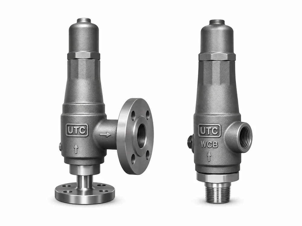
Safety valves and pressure relief valves protect equipment and people by opening automatically when system pressure exceeds a preset value, and closing again once pressure returns to a safe level. They are safety-critical devices: selection, sizing, setting and certification must be handled by qualified engineers according to the applicable code. UTC VALVES manufactures and supplies safety and relief valves against confirmed customer specifications.
Product specifications
Safety valve – Series SVT 20 (flanged)
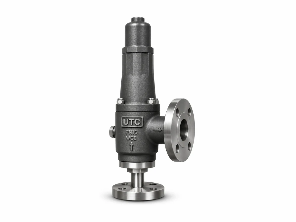
| Size range | 15 × 25 mm (½” × 1″) to 50 × 50 mm (2″ × 2″) |
|---|---|
| Pressure rating | Class 150 to 2500 |
| End connection | Flanged, ASME B16.5 |
| Seating | Metal and soft seating arrangement |
| Body | Investment casting; trims from certified bar stock (forged trims on request) |
| Versions | IBR / non-IBR (as per UTC VALVES catalogue) |
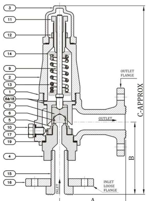
Dimensions & technical details (mm)
| Valve size (inlet × outlet) | A ±3.0 | B ±3.0 | C ±3.0 | Weight (kg) approx. |
|---|---|---|---|---|
| 15 × 25 | 105 | 116 | 300 | 7.5 |
| 20 × 25 | 105 | 116 | 300 | 7.5 |
| 25 × 25 | 105 | 116 | 300 | 7.5 |
| 25 × 40 | 105 | 116 | 300 | 9 |
| 40 × 50 | 110 | 130 | 366 | 16 |
| 50 × 50 | 110 | 130 | 366 | 16 |
All dimensions are in mm.
Material list
| No. | Part | Material (ASTM specification) |
|---|---|---|
| 1 | Body | ASTM A 216 Gr. WCB, ASTM A 351 Gr. CF8 / CF8M / CF3 / CF3M |
| 2 | Bonnet | ASTM A 216 Gr. WCB, ASTM A 351 Gr. CF8 / CF8M / CF3 / CF3M |
| 3 | Cap | ASTM A 216 Gr. WCB, ASTM A 351 Gr. CF8 / CF8M / CF3 / CF3M |
| 4 | Nozzle | SS 410 / 304 / 304L / 316 / 316L |
| 5 | Nozzle ring | ASTM A 216 Gr. WCB, ASTM A 351 Gr. CF8 / CF8M / CF3 / CF3M |
| 6 | Disc | SS 410 / 304 / 304L / 316 / 316L |
| 7 | Disc guide | SS 410 / 304 / 304L / 316 / 316L |
| 8 | Disc holder | SS 410 / 304 / 304L / 316 / 316L |
| 9 | Stem | SS 410 / 304 / 304L / 316 / 316L |
| 10 | Lock screw | SS 410 / 304 / 304L / 316 / 316L |
| 11 | Adjusting screw | SS 410 / 304 / 304L / 316 / 316L |
| 12 | Adjusting screw nut | SS 410 / 304 / 304L / 316 / 316L |
| 13 | Setting spring | Spring Steel / CS / SS / Alloy Steel |
| 14 | Spring washer | M.S. / SS 410 / 304 / 304L / 316 / 316L |
| 15 | Collar | SS 410 / 304 / 304L / 316 / 316L |
| 16 | Loose flange | SS 410 / 304 / 304L / 316 / 316L |
| 17 | Gasket (lock screw) | CAF / Graphite / PTFE |
| 18 | Gasket (guide) | CAF / Graphite / PTFE |
| 19 | Gasket (nozzle) | CAF / Graphite / PTFE |
Safety valve – Series SVT 22 (threaded)
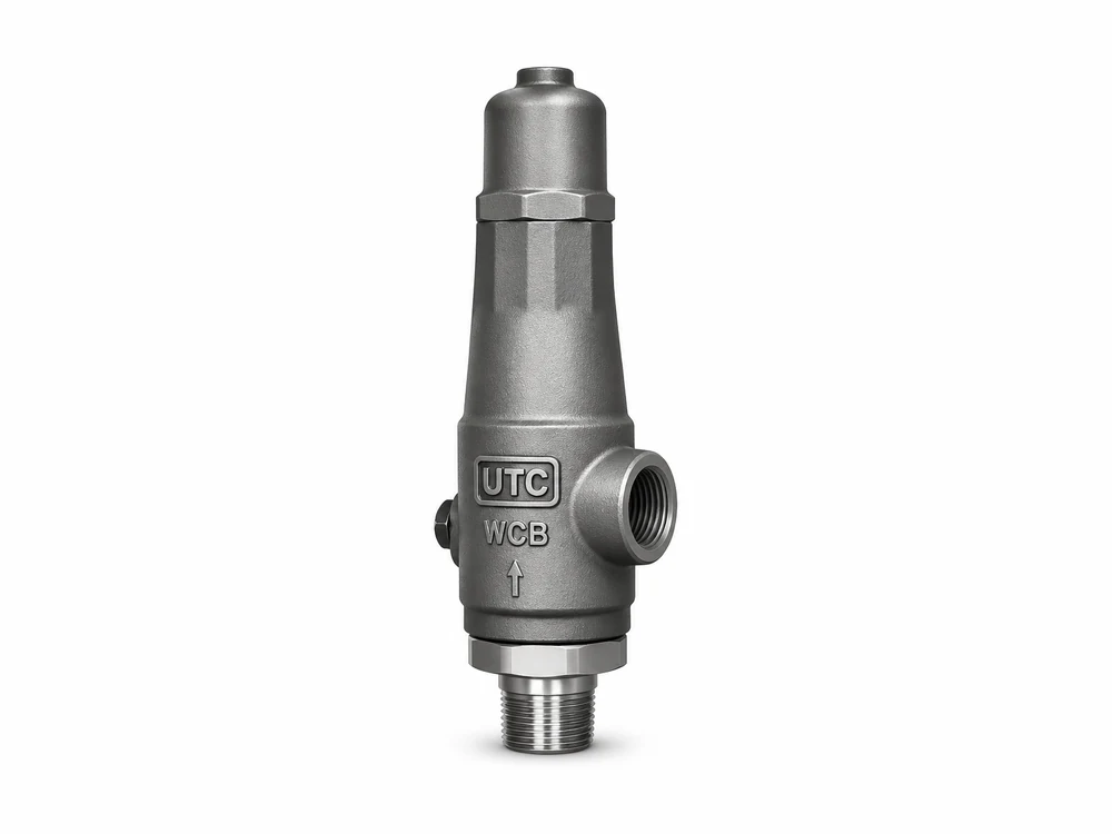
| Size range | 15 × 25 mm (½” × 1″) to 50 × 50 mm (2″ × 2″) |
|---|---|
| End connection | Threaded to ASME B1.20.1 – BSP, BSPT or NPT |
| Seating | Metal and soft seating arrangement |
| Versions | IBR / non-IBR (as per UTC VALVES catalogue) |
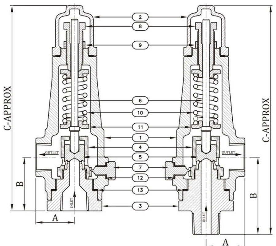
Dimensions & technical details (mm)
| Valve size (inlet × outlet) | A ±3.0 | B ±3.0 | C ±3.0 | Weight (kg) approx. |
|---|---|---|---|---|
| 15(F) × 25(F) | 46 | 64 | 245 | 5 |
| 20(F) × 25(F) | 46 | 64 | 245 | 5 |
| 25(F) × 25(F) | 46 | 64 | 245 | 5 |
| 40(F) × 50(F) | 67 | 87 | 312 | 8 |
| 50(F) × 50(F) | 67 | 87 | 312 | 8 |
Dimensions (continued)
| Valve size (inlet × outlet) | A ±3.0 | B ±3.0 | C ±3.0 | Weight (kg) approx. |
|---|---|---|---|---|
| 15(M) × 25(F) | 46 | 92 | 273 | 6 |
| 20(M) × 25(F) | 46 | 92 | 273 | 6 |
| 25(M) × 25(F) | 46 | 92 | 273 | 6 |
| 40(M) × 50(F) | 67 | 92 | 318 | 8.5 |
| 50(M) × 50(F) | 67 | 92 | 318 | 8.5 |
All dimensions are in mm.
Material list
| No. | Part | Material (ASTM specification) |
|---|---|---|
| 1 | Body | ASTM A 216 Gr. WCB, ASTM A 351 Gr. CF8 / CF8M / CF3 / CF3M |
| 2 | Cap | ASTM A 216 Gr. WCB, ASTM A 351 Gr. CF8 / CF8M / CF3 / CF3M |
| 3 | Nozzle | SS 410 / 304 / 304L / 316 / 316L |
| 4 | Nozzle ring | ASTM A 216 Gr. WCB, ASTM A 351 Gr. CF8 / CF8M / CF3 / CF3M |
| 5 | Disc | SS 410 / 304 / 304L / 316 / 316L |
| 6 | Stem | SS 410 / 304 / 304L / 316 / 316L |
| 7 | Lock screw | SS 410 / 304 / 304L / 316 / 316L |
| 8 | Adjusting screw | SS 410 / 304 / 304L / 316 / 316L |
| 9 | Adjusting screw nut | SS 410 / 304 / 304L / 316 / 316L |
| 10 | Setting spring | Spring Steel / CS / SS / Alloy Steel |
| 11 | Spring washer | M.S. / SS 410 / 304 / 304L / 316 / 316L |
| 12 | Gasket (lock screw) | CAF / Graphite / PTFE |
| 13 | Gasket (nozzle) | CAF / Graphite / PTFE |
Safety valve – Series SV 40 (full lift, flanged)
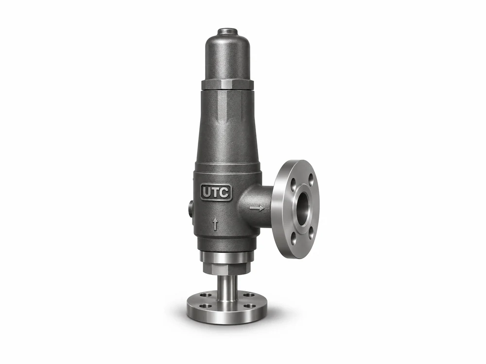
| Size range | 25 × 50 mm (1″ × 2″) to 250 × 350 mm (10″ × 14″) |
|---|---|
| Pressure rating | Class 150 to 2500, Table-H and Table-E |
| Design standard | API 520 / API 526 / API 527; ASME B16.5 and B16.34 |
| Arrangements | Packed lever, test gauge, bellows (for back pressure) |
| Versions | IBR / non-IBR (as per UTC VALVES catalogue) |
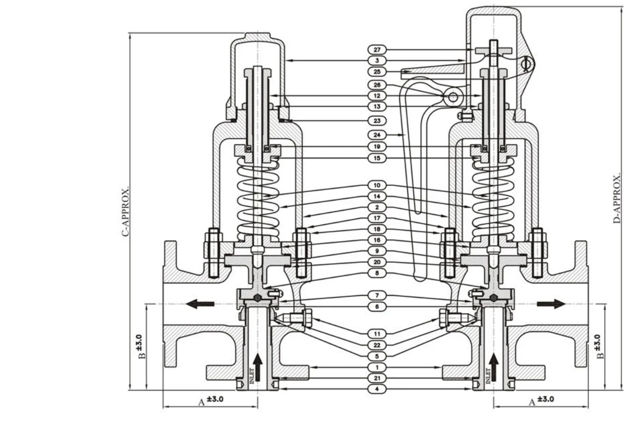
Dimensions & technical details (mm)
| Valve size (inlet × outlet) | A ±3.0 | B ±3.0 | C ±3.0 | D ±3.0 | Weight (kg) approx. |
|---|---|---|---|---|---|
| 25 × 50 | 115 | 105 | 430 | 460 | 20 |
| 40 × 50 | 120 | 124 | 460 | 490 | 23 |
| 40 × 80 | 124 | 130 | 530 | 490 | 30 |
| 50 × 80 | 124 | 133 | 540 | 575 | 36 |
| 80 × 100 | 162 | 155 | 590 | 620 | 50 |
| 100 × 150 | 229 | 181 | 830 | 900 | 149 |
| 150 × 200 | 240 | 240 | 990 | 1050 | 210 |
| 200 × 250 | 280 | 276 | 1400 | 1470 | 325 |
| 250 × 350 | 395 | 385 | 1600 | 1670 | 950 |
All dimensions are in mm.
Material list
| No. | Part | Material (ASTM specification) |
|---|---|---|
| 1 | Body | ASTM A 216 Gr. WCB, ASTM A 351 Gr. CF8 / CF8M / CF3 / CF3M |
| 2 | Bonnet (open / closed) | ASTM A 216 Gr. WCB, ASTM A 351 Gr. CF8 / CF8M / CF3 / CF3M |
| 3 | Cap (open / closed) | ASTM A 216 Gr. WCB, ASTM A 351 Gr. CF8 / CF8M / CF3 / CF3M |
| 4 | Nozzle | ASTM A 351 CA15 / CF8 / CF8M / CF3 / CF3M |
| 5 | Nozzle ring | ASTM A 351 CA15 / CF8 / CF8M / CF3 / CF3M |
| 6 | Disc | SS 410 / 304 / 304L / 316 / 316L |
| 7 | Reaction hood | ASTM A 351 CA15 / CF8 / CF8M / CF3 / CF3M |
| 8 | Disc holder | ASTM A 351 CA15 / CF8 / CF8M / CF3 / CF3M |
| 9 | Guide | ASTM A 351 CA15 / CF8 / CF8M / CF3 / CF3M |
| 10 | Stem | SS 410 / 304 / 304L / 316 / 316L |
| 11 | Lock screw | SS 410 / 304 / 304L / 316 / 316L |
| 12 | Adjusting screw | SS 410 / 304 / 304L / 316 / 316L |
| 13 | Adjusting screw nut | SS 410 / 304 / 304L / 316 / 316L |
| 14 | Setting spring | Spring Steel / Stainless Steel / Alloy Steel |
| 15 | Upper spring washer | M.S. / SS 410 / 304 / 304L / 316 / 316L |
| 16 | Lower spring washer | M.S. / SS 410 / 304 / 304L / 316 / 316L |
| 17 | Studs | B7 / B8 / B8M / L7 |
| 18 | Nuts | 2H / 8 / 8M / 7 |
| 19 | Thrust bearing | As per standard manufacturer |
| 20 | Gasket (body) | CAF / Graphite / PTFE |
| 21 | Gasket (nozzle) | CAF / Graphite / PTFE |
| 22 | Gasket (lock screw) | CAF / Graphite / PTFE |
| 23 | Gasket (cap) | CAF / Graphite / PTFE |
| 24 | Lever | ASTM A 216 Gr. WCB, A 351 CF8, CF8M, SG Iron |
| 25 | Fork | ASTM A 216 Gr. WCB, A 351 CF8, CF8M, SG Iron |
| 26 | Lever & fork pin | M.S. / SS 304 / 316 |
| 27 | Stem nut | M.S. / SS 304 / 316 |
| 28 | Bellows (if required) | SS 304 / 304L / 316 / 316L / Inconel |
How it works
A spring holds the disc against the nozzle. When inlet pressure reaches the set pressure, the force on the disc overcomes the spring and the valve opens to discharge fluid. Key terms include set pressure, overpressure (pressure rise above set while relieving) and blowdown (the difference between set pressure and reseating pressure).
Types and configurations
- Safety valve – rapid full-lift (pop) action, typically for steam, gas and vapour
- Relief valve – opens in proportion to overpressure, typically for liquids
- Safety relief valve – suitable for either duty, depending on the application
- Conventional spring-loaded, balanced bellows and pilot-operated designs
- Full-lift and low-lift designs
Construction and design features
- Adjustable set pressure within the spring range (set and sealed before dispatch, where applicable)
- Open or closed bonnet options
- Lifting lever (easing gear) where required by code or application
- Balanced bellows to reduce the effect of back pressure
- Orifice sizes selected according to the required relieving capacity
Materials of construction
- Carbon steel bodies (e.g. ASTM A216 WCB)
- Stainless steel bodies and trims (e.g. ASTM A351 CF8M)
- Alloy steel for high-temperature service
- Spring materials selected for temperature – to be confirmed per datasheet
- Availability of each grade is subject to confirmation by UTC VALVES for every enquiry.
Material grades listed are those commonly specified in industry for this valve type. Availability of each grade is subject to confirmation by UTC VALVES for every enquiry.
End connections
- Flanged inlet and outlet (outlet typically larger than inlet)
- Threaded ends on small sizes
- Other connections on request
Pressure classes and standards
Pressure classes offered by UTC VALVES: listed for each model in the product specifications below.
Standards commonly referenced for this valve type include ASME Boiler & Pressure Vessel Code Sections I and VIII, API 526 (flanged steel pressure relief valves), API 527 (seat tightness), API 520/521 (sizing, selection and installation guidance) and ISO 4126. These are industry references; they do not indicate that UTC VALVES or its products hold certification. Compliance documents are provided per order where available.
Industrial applications
- Boiler and steam system protection
- Pressure vessel and heat exchanger protection
- Compressor and pump discharge protection
- Storage tank and process line overpressure protection
Industries served
- Power generation
- Oil & gas
- Refining & petrochemicals
- Chemical processing
- Pharmaceutical & food processing
Information to include in your enquiry
A complete enquiry helps us respond with an accurate offer for safety valves:
- Valve type and configuration
- Nominal size (NPS / DN)
- Pressure class or rating
- Body, trim and seat materials
- End connection and facing
- Operator: lever, handwheel, gear or actuator
- Service fluid, design pressure and temperature
- Applicable standard or project specification
- Quantity and required delivery date
- Inspection, testing and documentation requirements (e.g. material test certificates, third-party inspection)
Safety Valves: frequently asked questions
What is the difference between a safety valve and a relief valve?
A safety valve opens rapidly to full lift and is generally used for compressible fluids such as steam and gas. A relief valve opens gradually in proportion to overpressure and is generally used for liquids.
Who should size a safety valve?
A qualified engineer, using the governing code and the system data: required relieving capacity, set pressure, back pressure, fluid properties and temperature.
Can UTC VALVES supply set and certified safety valves?
Yes. Safety valves can be supplied set to the required set pressure and tested before dispatch, with a test certificate. Please state the set pressure, required code (for example IBR, ASME Section VIII or API 526) and any third-party inspection in your enquiry; code certification is confirmed in the quotation.
Related valve categories
Request a quote for safety valves
Send your specification, datasheet or bill of materials. Our team reviews every enquiry and responds with availability and a quotation.